This section uses two examples to quickly configure ESP8266-Based serial WiFi shield, so as to achieve Serial WiFi transparent communication.
Preparation work: configuration WiFi working mode
For serial WiFi shield, the factory default working mode is configuration mode. Transparent communication configuration should be done firstly.
Attention: if the shiled has been configured to operate in other working mode, the module shield can enter configuration mode through the following ways. One is that press KEY button for more than 1 second. The other one is that send “!@!” to the serial WiFi shield through serial port.
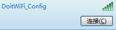
Step 1: Power the serial WiFi shield, and find the WiFi signal. The SSID is "DoitWiFi_Config". The Password is "12345678."
Step 2: Open the browser, and enter WiFi IP address: 192.168.4.1. The configuration page is shown as below.
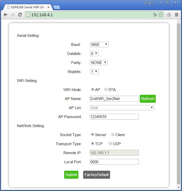
Built-in WebServer in the serial WiFi shield supports serial parameters configuration, network parameter configuration. And It also supports automatic or manual AP scan.
Step 3: press “submit”.
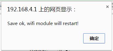
After submission, the serial wifi shield will automatically reboot into AP mode, and configure as:
The serial port parameters to 9600, n, 8, 1,
WiFi working mode: AP;
SSID: "DoitWiFi_Ser2Net";
Password: "12345678."
TCP Server, and port is 9000.
This is also the factory default configuration. You also can press "FactorDefault" to achieve the configuration as previously described.
Example 1: Arduino to WiFi communication
Step 1: plug the srial WiFi shield into the Arduino Uno board. The dual-ports DIP switch is switched to “OFF” position as to disconnect the serial port connection within ESP8266 and Arduino .
(Attention: when downloading arduino program with IDE, arduino serial port should NOT be used. Arduino Uno only has one serial port for downloading program, for the reason that the dual-port switches should switch to “OFF” position to disconnect the serial port of ESP8266. )
Step2: program arduino Uno, and the example code is shown as below:
1.    void setup()
2.    {
3.      Serial.begin(9600);
4.    }
5.    void loop()
6.    {
7.       delay(1000);
8.       Serial.println("hello ESP8266 WiFi"); //output the serial data
9.    }
Step3: Switch the dual-port switch to “ON” position. Now, the ESP8266 is connected with Arduino Uno.
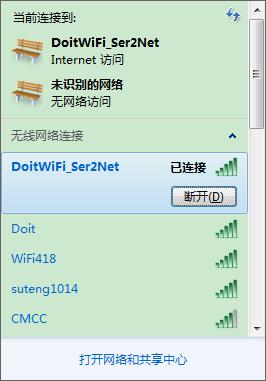
Step4: Find the WiFi signal “DoitWiFi_Ser2Net” with computer or mobile phone. The WiFi password is “12345678”.
Step5:run the TCP/UDP Debugging software.(Software Download Link: http://bbs.doit.am/forum.php?mod=viewthread&tid=174&page=1&extra=#pid206)
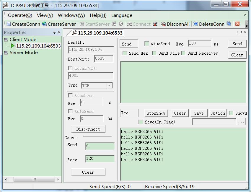
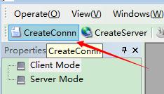
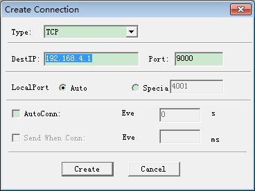
Establish a TCP client connection, and the Destination IP address is 192.168.4.1, Port number is 9000.Local port is configured to “Auto”.
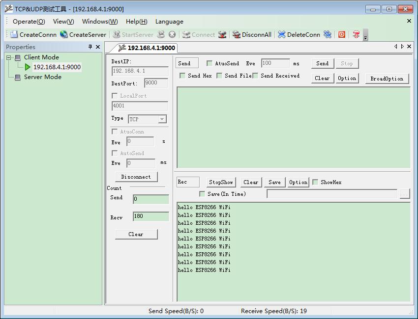
Once connection is build successfully, the software shows the transported data from serial WiFi shield every one second. Therefore, Arduino can send the serial data to the network.
example2: communicate with remote server
Here, Doit free public WiFi network TCP tool is used to accomplish the example.
Step 1: Get a temporary IP address and port from the TCP server. Here, the obtained IP address is : “115.29.109.104”, and the port number is “6533”.
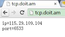
(Note: IP address and port number can be obtained in http://tcp.doit.am)
Step 2: enter the configuration mode. After powering the serial WiFi shield, press KEY button for more than one second. Connect the SSID named “DoitWiFi_Config” with the passward “12345678”. Then, enter "192.168.4.1" in the browser.
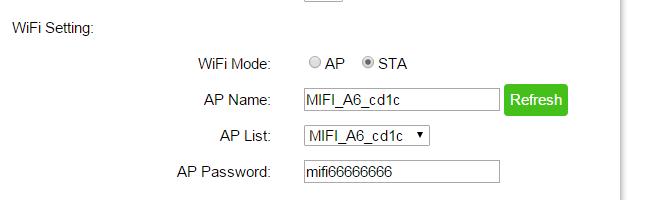
Step 3: Configure the serial WiFi shield to node mode (STA mode), so as to connect to a wireless router, as below:
“WiFi Mode”: STA;
Here a wireless router named “MIFI_A6_cd1c” is used and the password is “mifi66666666”.
WebServer will automatically refresh the current ESP8266 searched AP list when loading the page. When selecting "STA", "Refresh" button is enabled to refresh the WiFi scan results.
Step 4: Configure network parameters.
Socket Type: “Client”。
Transport Type: “TCP”。
Remote IP:“115.28.109.104”
Remote Port:“6533”。
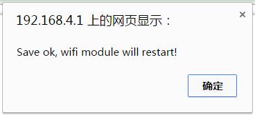
Step 5: press “Submit”.
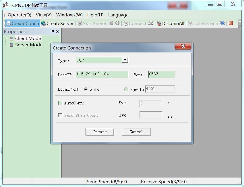
Step 6: run the TCP/UDP debug software.
Establish a TCP Client connection. The destination IP address is 115.29.109.104, Port number is 6533. Local port is configured to “Auto”.
Step 7: the software shows the transported data from serial WiFi shield through the wireless router. Therefore, Arduino can send the serial data to the network in STA mode.