After install the USB to UART Bridge VCP driver. You can use WiFiMCU STUDIO to test WiFiMCU simplily and quickly. Here are the instructions to quickly start with WiFiMCU.
1 Prepare
WiFiMCU STUDIO is an open source develop tool for WiFiMCU. The latest executable program can be downloaded at:
https://github.com/SmartArduino/WiFiMCU-STUDIO/releases
You can pull the source code from:
https://github.com/SmartArduino/WiFiMCU-STUDIO
2 Power Up
Power up the WiFiMCU with a Micro USB Cable.
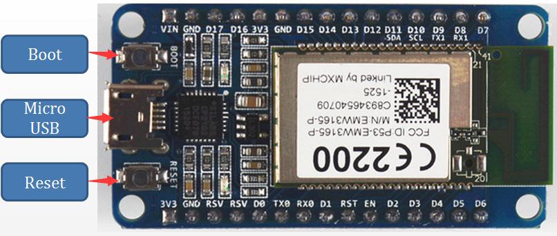
Press “Reset” button to restart WiFiMCU.
Press “Boot” button while power up or press “Reset” button to enter into bootloader mode.
3 Check the COM Port
Go to “Start Memu”-> “Control Pannel”->”Device Manager” to check the Serial COM Port.
4 Run WiFiMCU STUDIO
Click “Scan Port” button to scan the existing serial com ports in the computer.
Make sure choose the right serial port of WiFiMCU, then click “Open” to open the serial com port. The default serial com parameters for WiFiMCU is 115200bps, 8 data bits, none check, one stop bit.
You can type a command in the right black textbox just like what your do in other serial tools such as “SecureCR”, “PuTTY”.
Type ”mcu.reboot()” in the command textbox and press enter, The commands are go into the Lua interpreter, and executed. The results will be shown in the textbox.
You will see like this:

You can also just click “Reboot” button to do the same thing. Other common commands:
“collectgarbage()”, collect the garbage in Lua interpreter.
“=mcu.tick()”, get the current time tick of the MCU (ms) since startup.
“=mcu.mem()”, get the memory status.
All the commands for WiFiMCU can be found in the reference book:
https://github.com/SmartArduino/WiFiMCU/tree/master/Document/
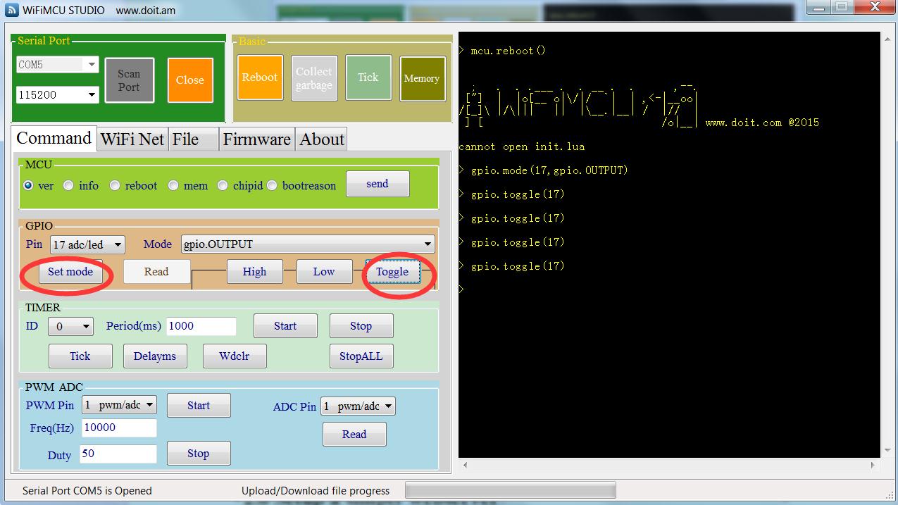
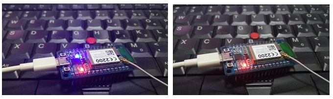
5 Toggle LED on WiFiMCU board
There is a LED connected to D17 on WiFiMCU board. You can toggle it very simply using WiFiMCU STUDIO.
STEP1, Switch to “Command” tabpage.
STEP2, Choose GPIO Pin “17 adc/led” in “GPIO” groupbox. Then choose “gpio.OUTPUT” in mode combox list.
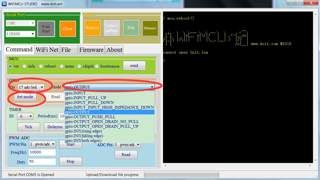
STEP 3, click “Set mode”, command string “gpio.mode(17,gpio.OUTPUT)” will be sent to WiFiMCU and executed. The LED on WiFiMCU board will be lighted on or off after you click“Toggle” button.
You can test the other gpio functions such as input/ interrup / pwm/ adc in the “Command” tabpage.
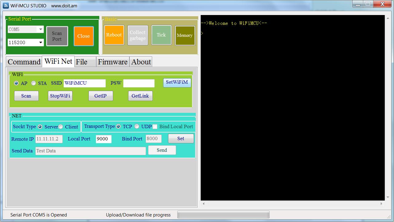
6 Start AP mode
The WiFi interface of WiFiMCU could work in either Access Point(AP), Station(STA), or AP+STA mode. The instructions below will setup a WiFi interface in AP mode for example.
STEP 1, Switch to “WiFi Net” tabpage.
STEP 2, Choose “AP”, fill the SSID and PSW textbox. It will be “WiFiMCU_Wireless” for SSID and empty for PSW in default. Click “Set” to send the command string.
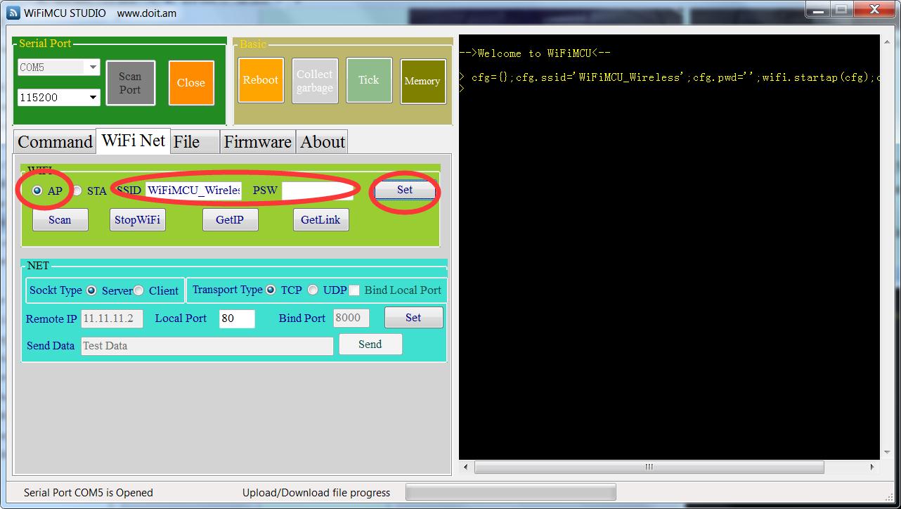
STEP 3, A WiFi interface with SSID: “WiFiMCU_Wireless” will be setup.
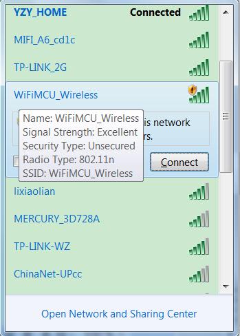
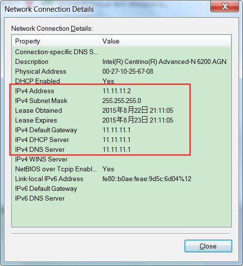
STEP 4, You can connected to the Open sercurity WiFi. The default IP for WiFiMCU is “11.11.11.1”. The IP could be customized, check WiFiMCU Reference Book for more details.
7 Setup a simply webserver
WiFiMCU can be configured to support TCP/UDP Server and Client. It’s very easy to setup sockets and connections. A simply webserver will be created by using Lua scripts in this section. We will use the WiFiMCU STUDIO to upload a Lua scripts file and run it.
STEP 0, Make sure the WiFiMCU is running in AP mode or STA mode or AP+STA mode, if you are strange for this, follow the instructions in 2.5 section.
STEP 1, Save the Lua scripts below as “webserver.lua”.
1.skt = net.new(net.TCP,net.SERVER)
2.net.on(skt,"accept",function(clt,ip,port)
3.print("accept ip:"..ip.." port:"..port.." clt:"..clt)
4.net.send(clt,[[HTTP/1.1 200 OK
5.Server: WiFiMCU
6.Content-Type:text/html
7.Content-Length: 28
8.Connection: close
9.
10.
11.《h1》 Welcome to WiFiMCU! 《/h1》 ]])
12.end)
13.net.start(skt,80)
STEP 2, Switch to “File” tabpage.
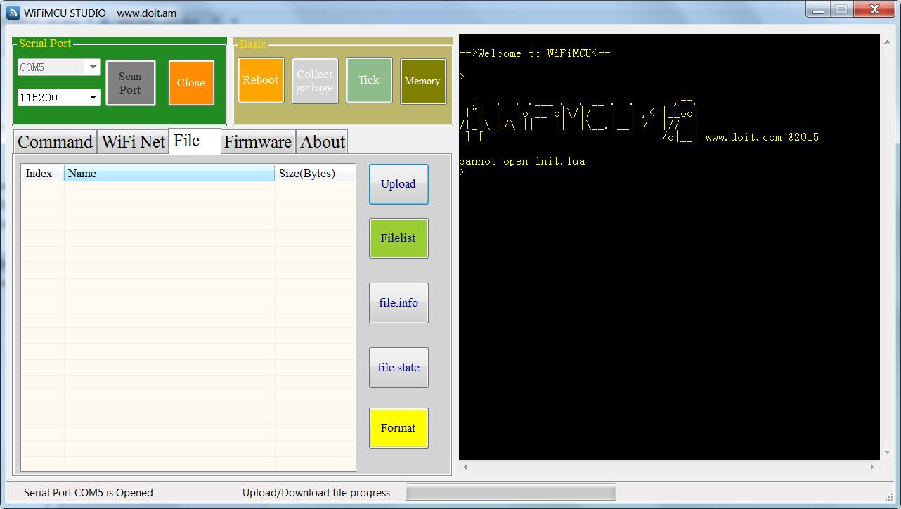
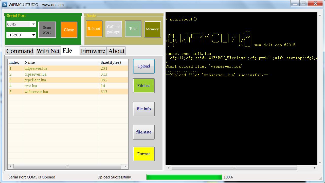
STEP 3, Click “Upload” button to choose “webserver.lua”.

STEP 4, The uploading procedure will be started automatically. If uploading successfully, the files stored in WiFiMCU will be listed in the listbox.
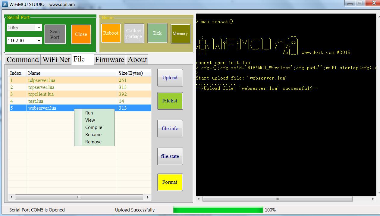
STEP 5, Choose “webserver.lua” in the listbox. Right Click the mouse, a submenu list will be shown. Click “Run” to run the script. Command string “dofile('webserver.lua')” will be sent to Lua interpreter.
You can test the other operations for the selected file freely.
STEP 6, Use a PC or a smart Phone connect to the AP that WiFiMCU made. For example, such as “WiFiMCU_Wireless” we made in above section.
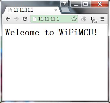
STEP 7, Open a browser, and type ”11.11.11.1” in the address field. You will get: